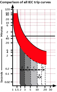
Origin of trip curve
The concept of trip curve originated in the IEC world and is used to classify micro-circuit breakers (B, C, D, K and Z) from IEC standards. The standard defines lower and upper limits for trips, but manufacturers have the flexibility to determine the precise specifications within these thresholds that would cause their products to trip. Trip diagrams show the tolerance zones where the manufacturer can set the trip points of its circuit breaker.
The characteristics and applications of each curve, from most sensitive to least sensitive, are:
Z: Trip at 2 to 3 times rated current, suitable for highly sensitive applications such as semiconductor equipment
B: Trip at 3 to 5 times rated current
C: Trip at 5 to 10 times rated current, suitable for medium inrush current
K: Trip at 10 to 14 times rated current, suitable for loads with high inrush current, mainly used for motors and transformers
D: Trip at 10 to 20 times rated current, suitable for high starting current
Reviewing the “Comparison of all IEC Trip curves” chart, you can see that higher currents trigger faster trips.
The ability to withstand impulse current is an important consideration in the selection of trip curves. Certain loads, especially motors and transformers, experience transient changes in current, known as impulse current, when the contacts are closed. Faster protection devices, such as b-trip curves, would recognize this influx as a failure and turn on the circuit. For these types of loads, trip curves with high magnetic trip points (D or K) can “pass” through the instantaneous current influx, protecting the circuit from false trip

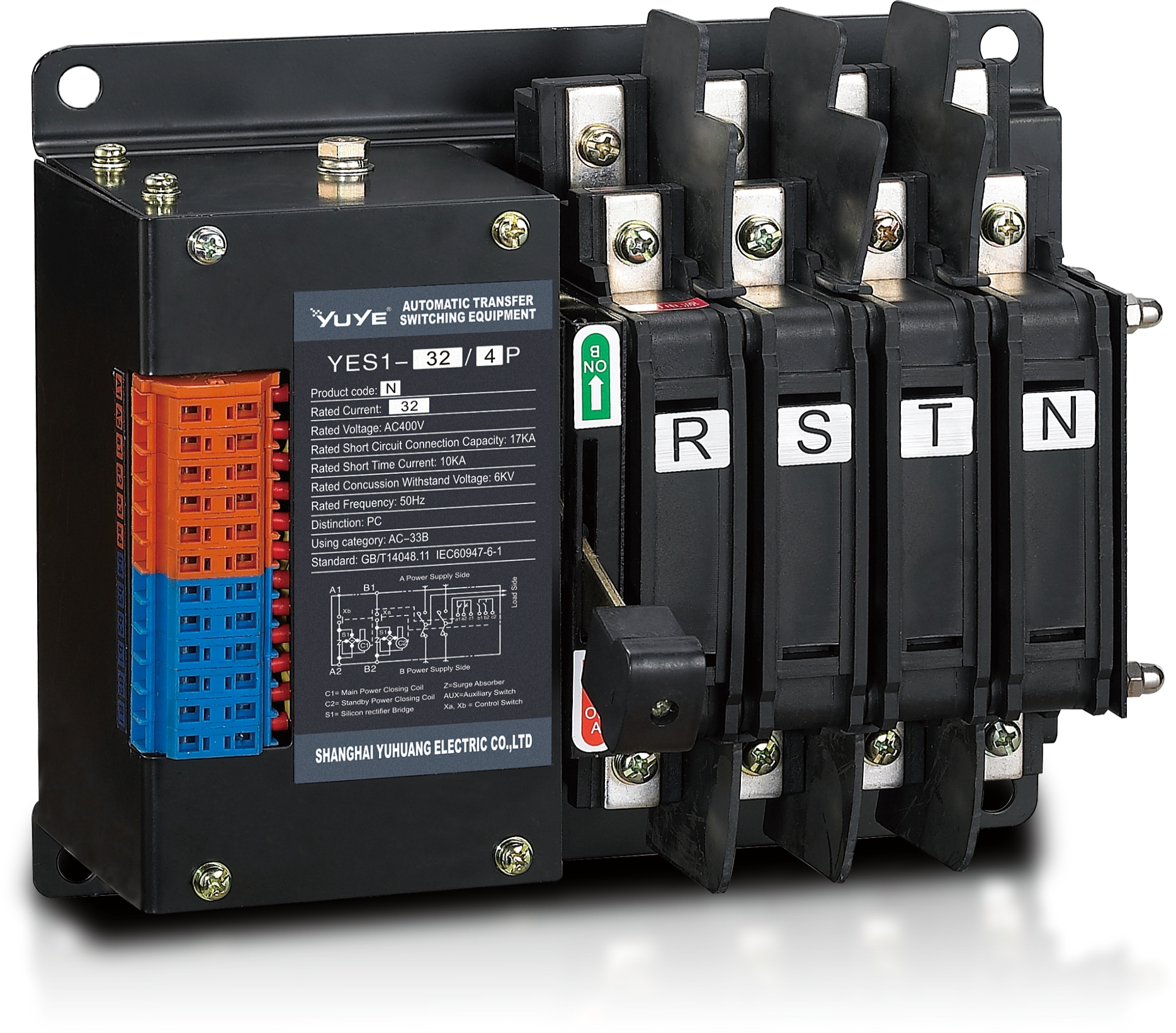 PC Automatic transfer switch YES1-32N
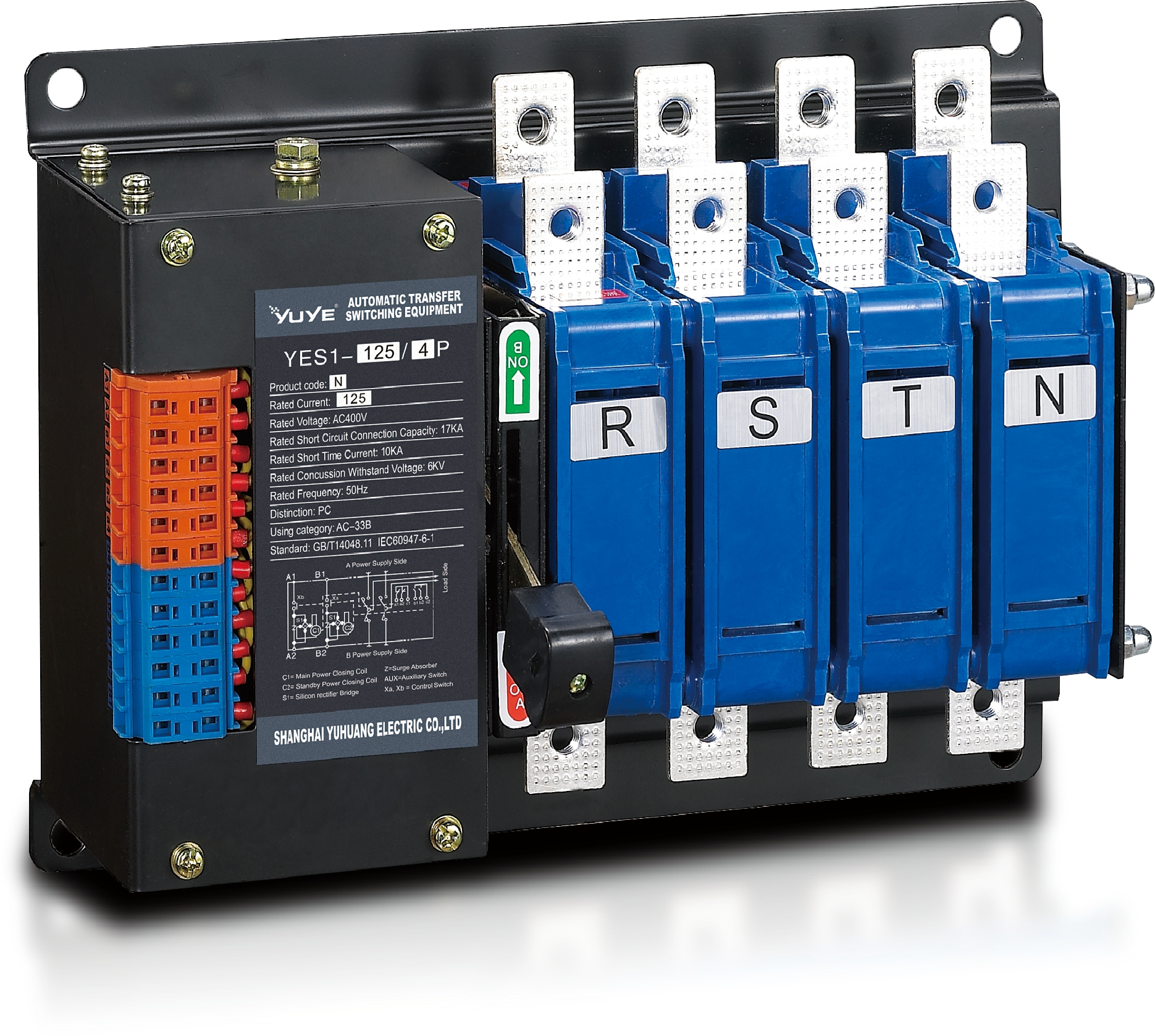 PC Automatic transfer switch YES1-125N
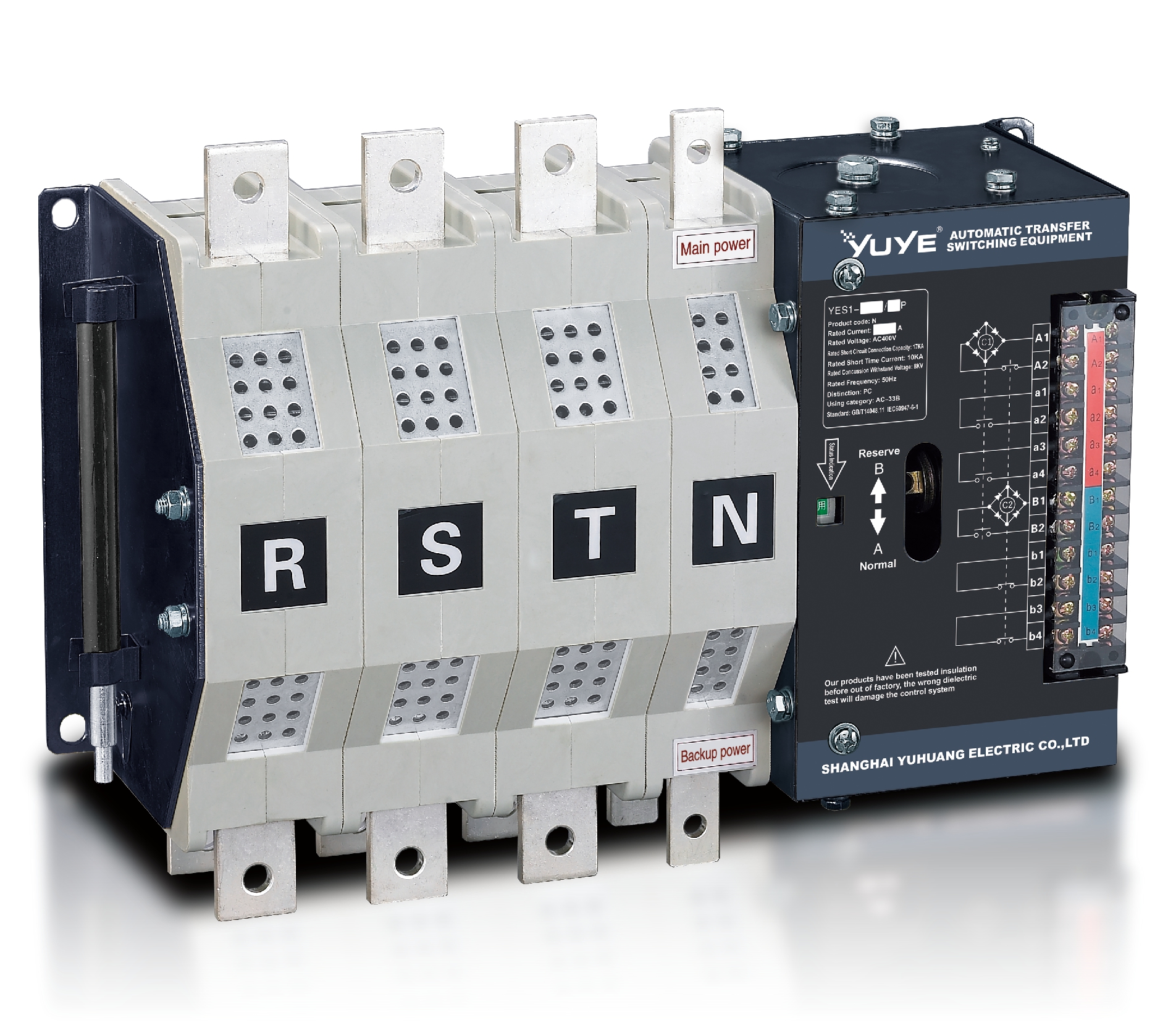 PC Automatic transfer switch YES1-400N
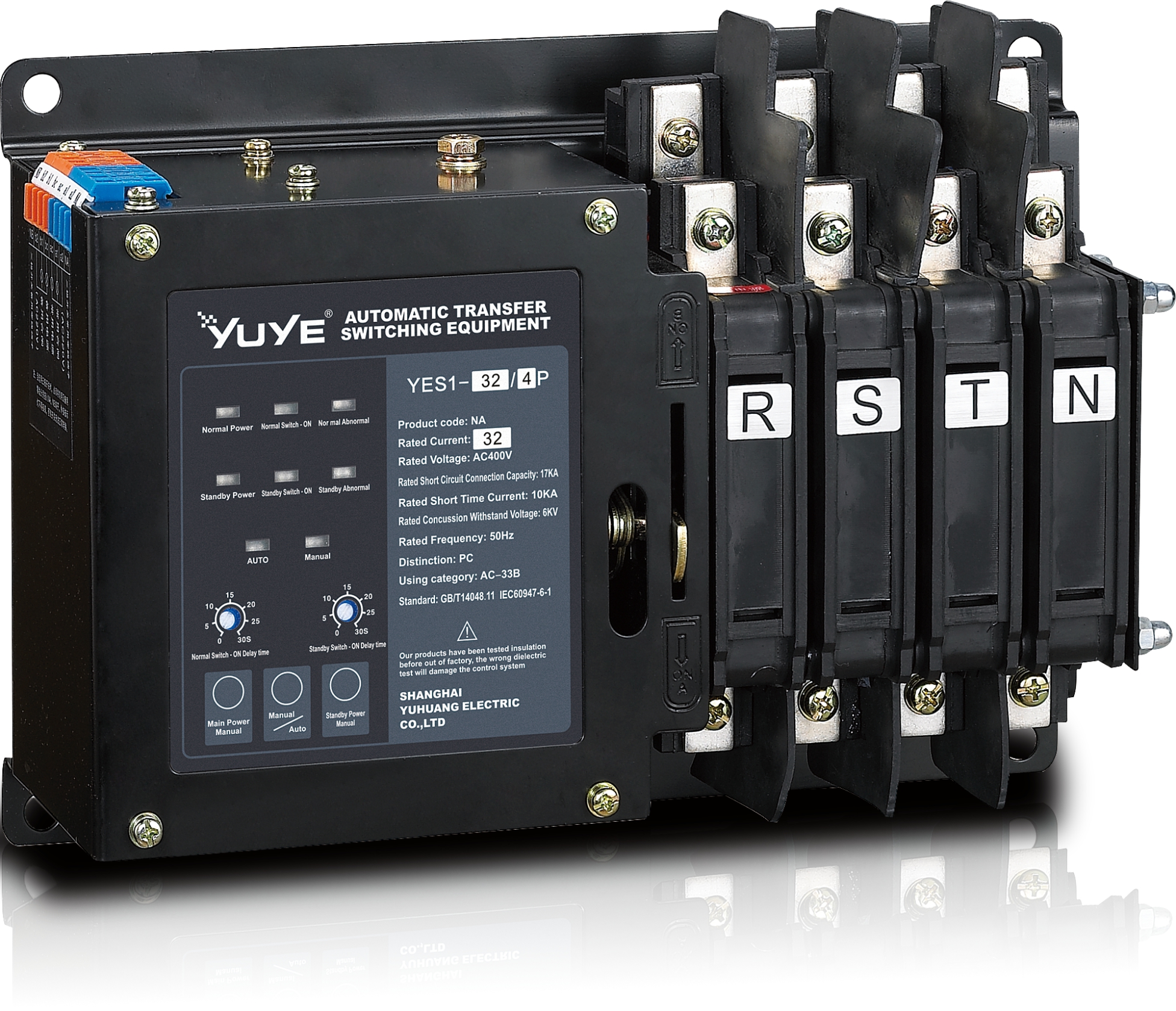 PC Automatic transfer switch YES1-32NA
 PC Automatic transfer switch YES1-125NA
 PC Automatic transfer switch YES1-400NA
 PC Automatic transfer switch YES1-100G
 PC Automatic transfer switch YES1-250G
 PC Automatic transfer switch YES1-630G
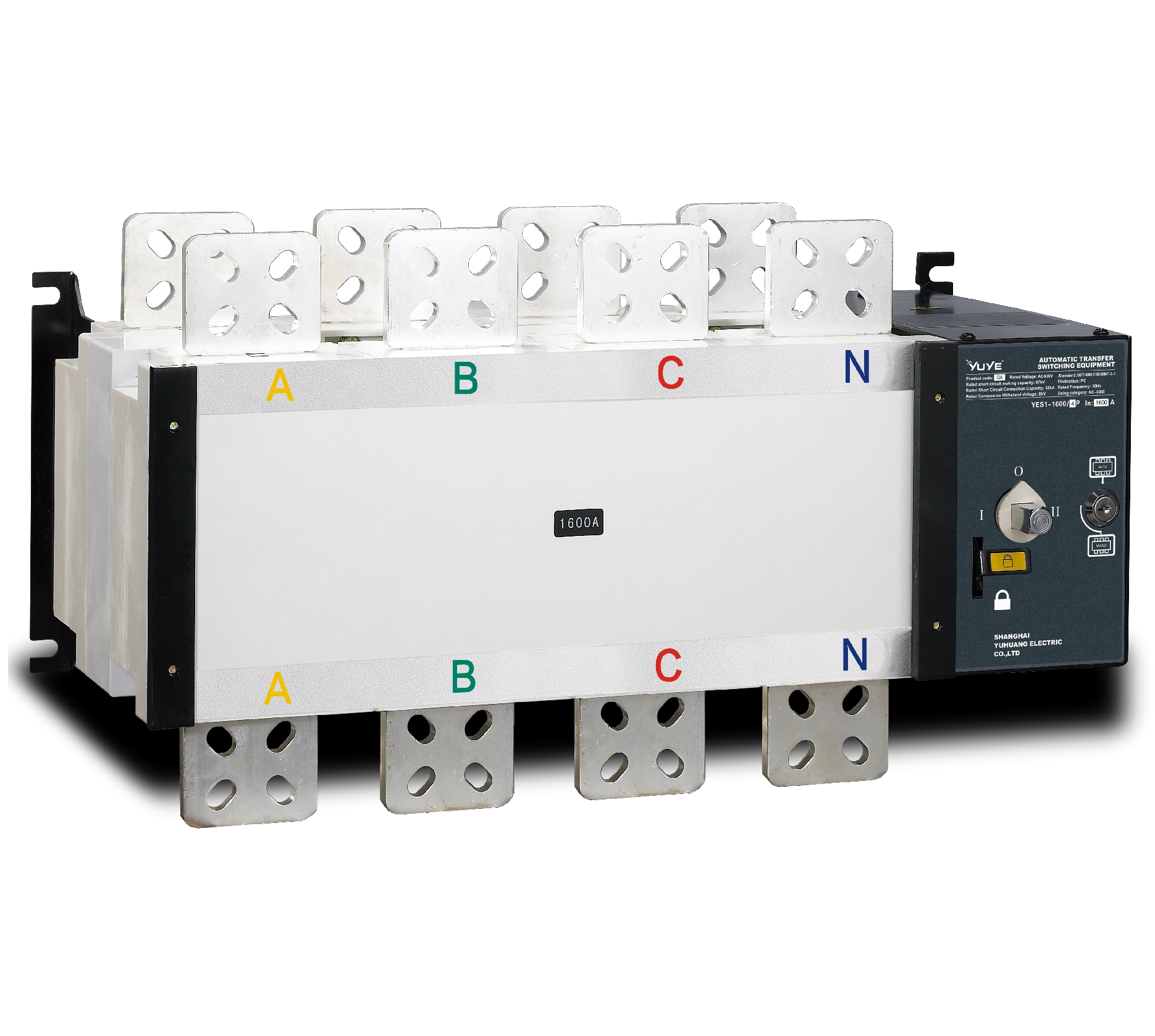 PC Automatic transfer switch YES1-1600G
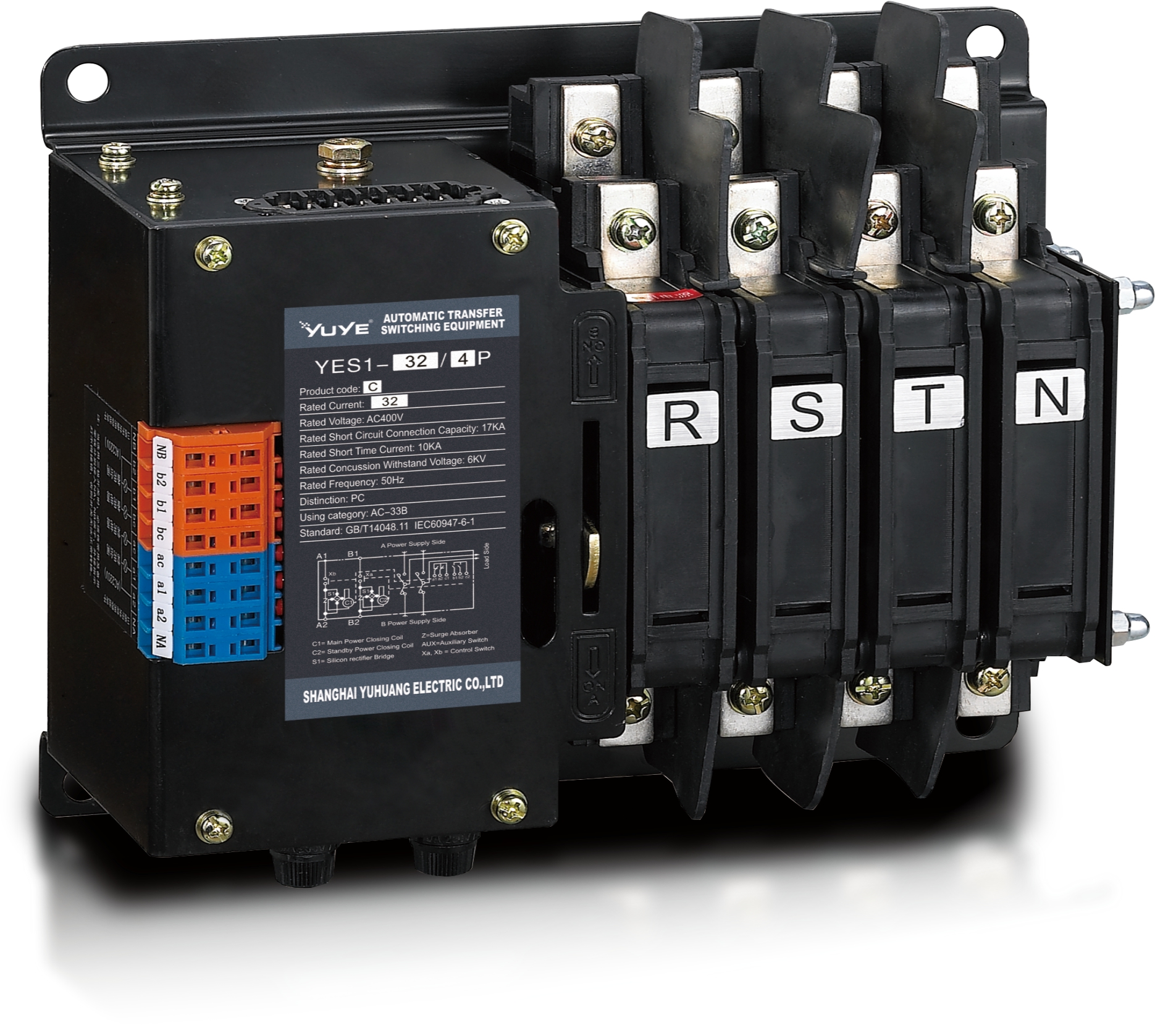 PC Automatic transfer switch YES1-32C
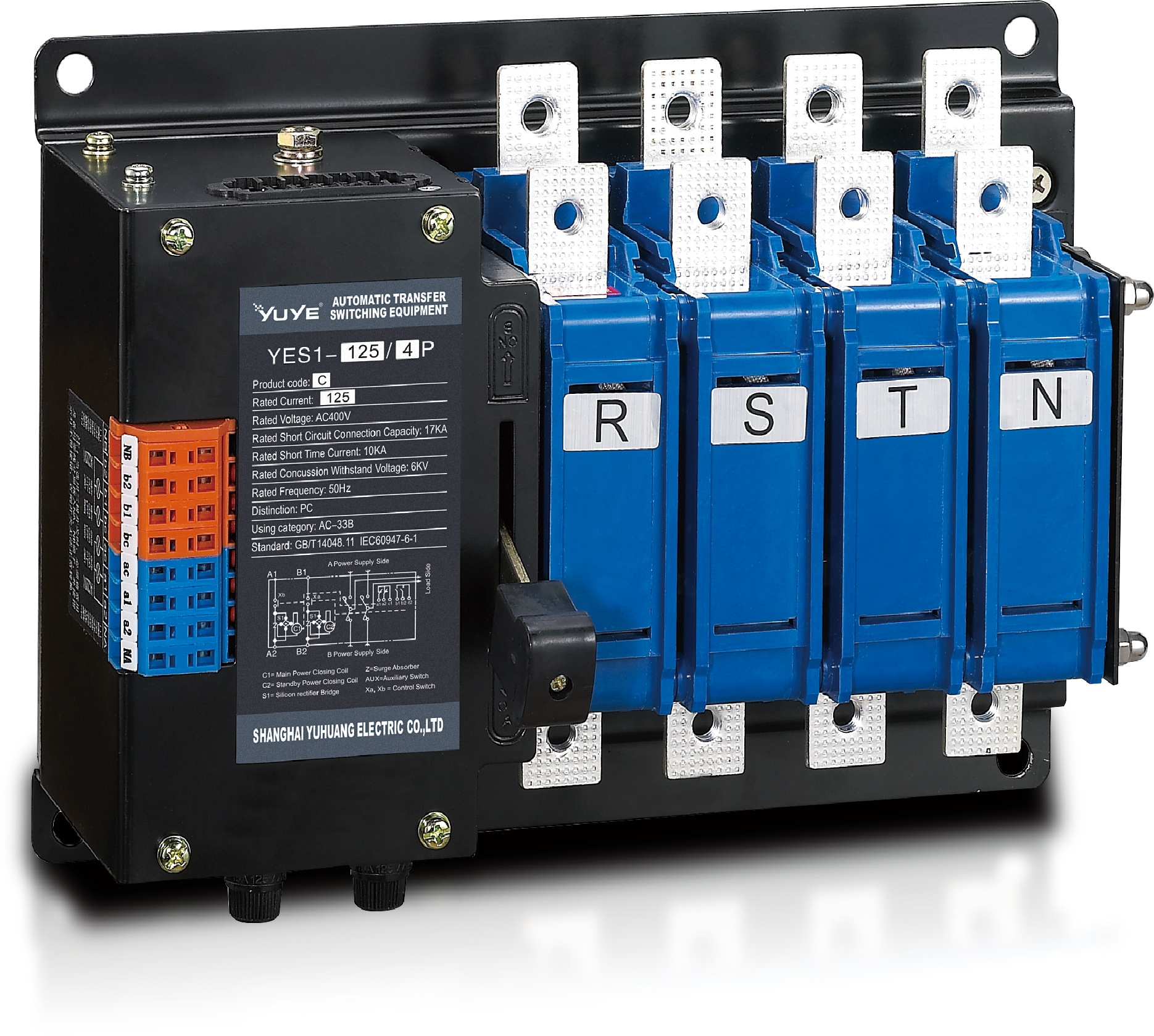 PC Automatic transfer switch YES1-125C
 PC Automatic transfer switch YES1-400C
 PC Automatic transfer switch YES1-125-SA
 PC Automatic transfer switch YES1-1600M
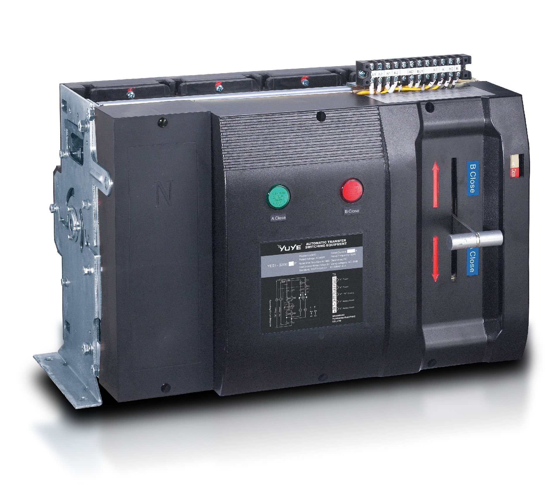 PC Automatic transfer switch YES1-3200Q
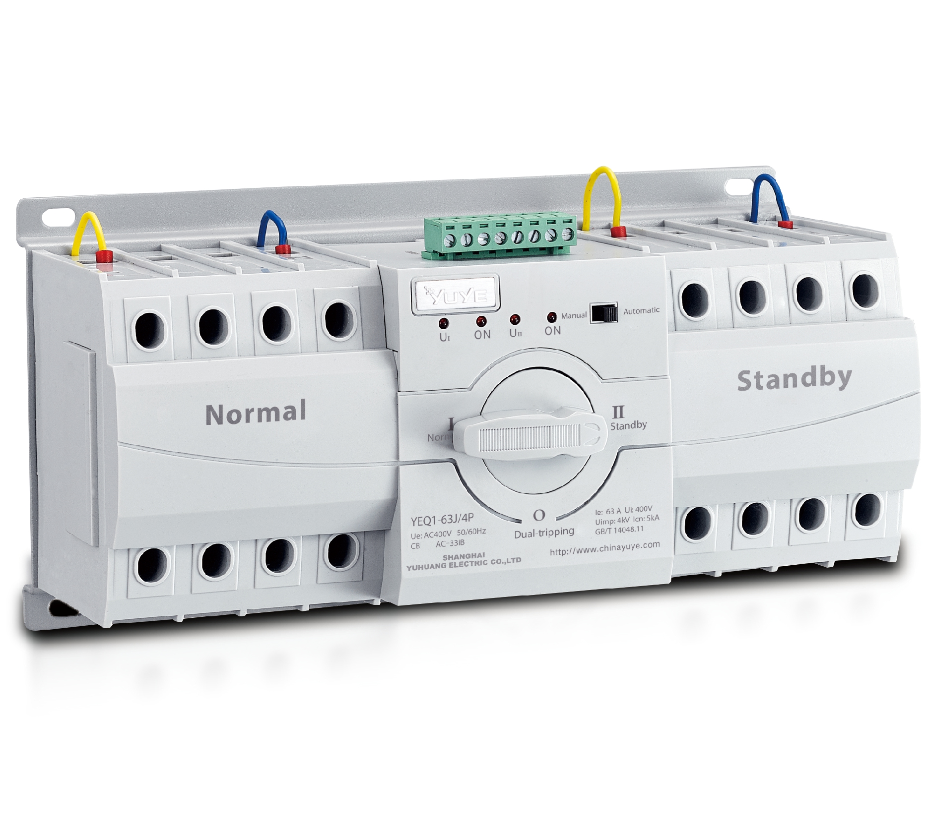 CB Automatic transfer switch YEQ1-63J
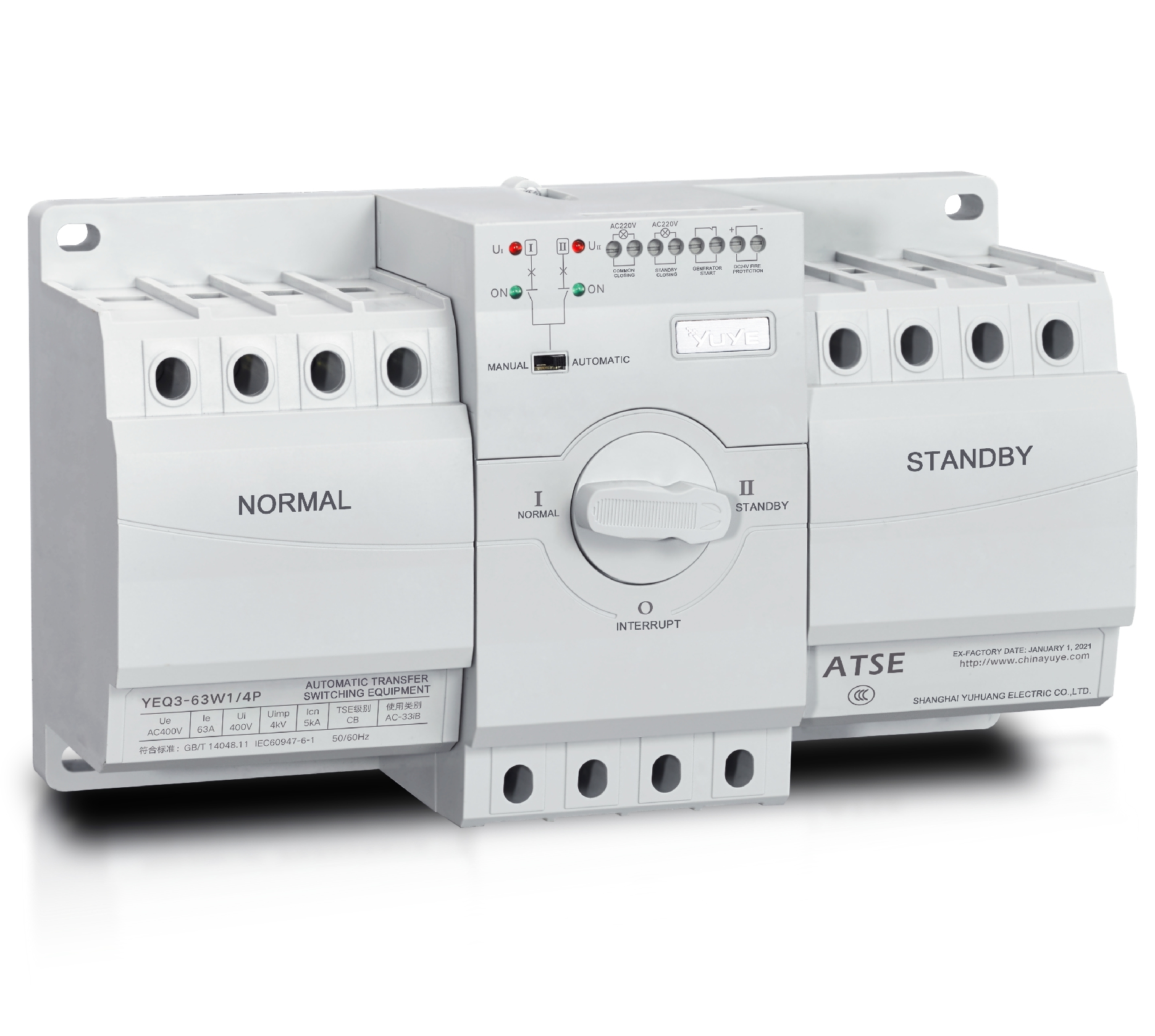 CB Automatic transfer switch YEQ3-63W1
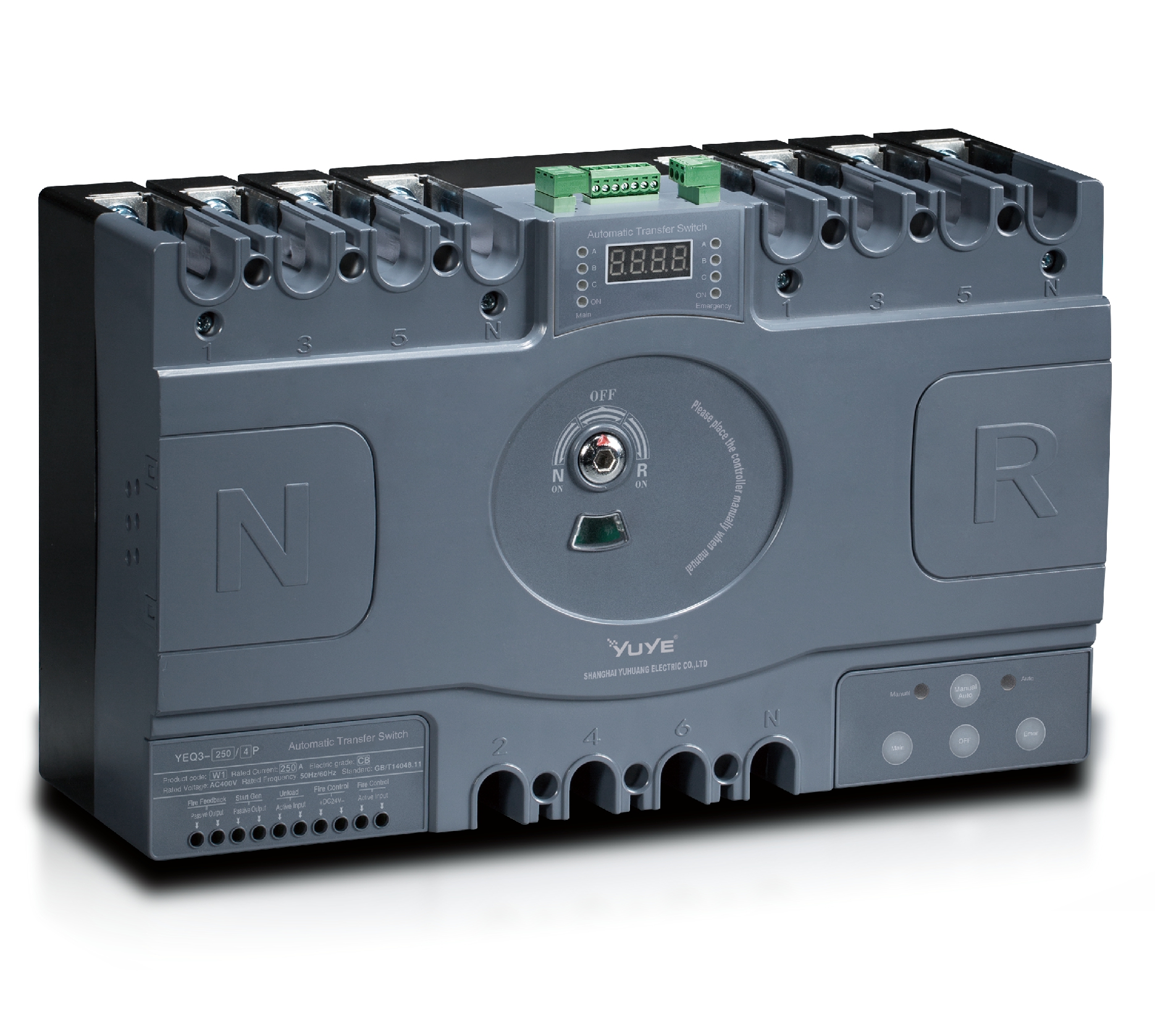 CB Automatic transfer switch YEQ3-125
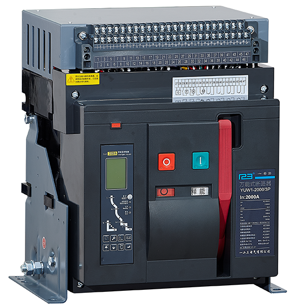 Air Circuit Breaker YUW1-2000/3P Fixed
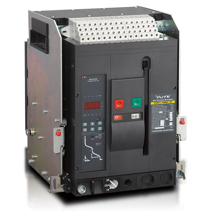 Air Circuit Breaker YUW1-2000/3P Drawer
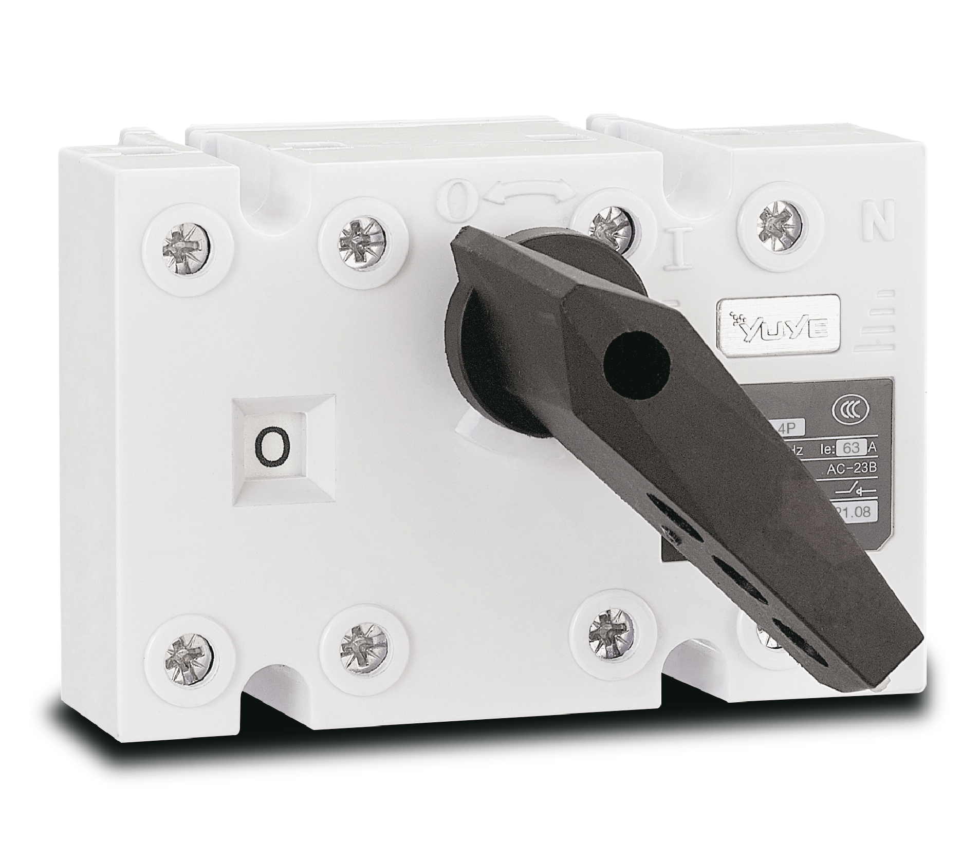 Load isolation switch YGL-63
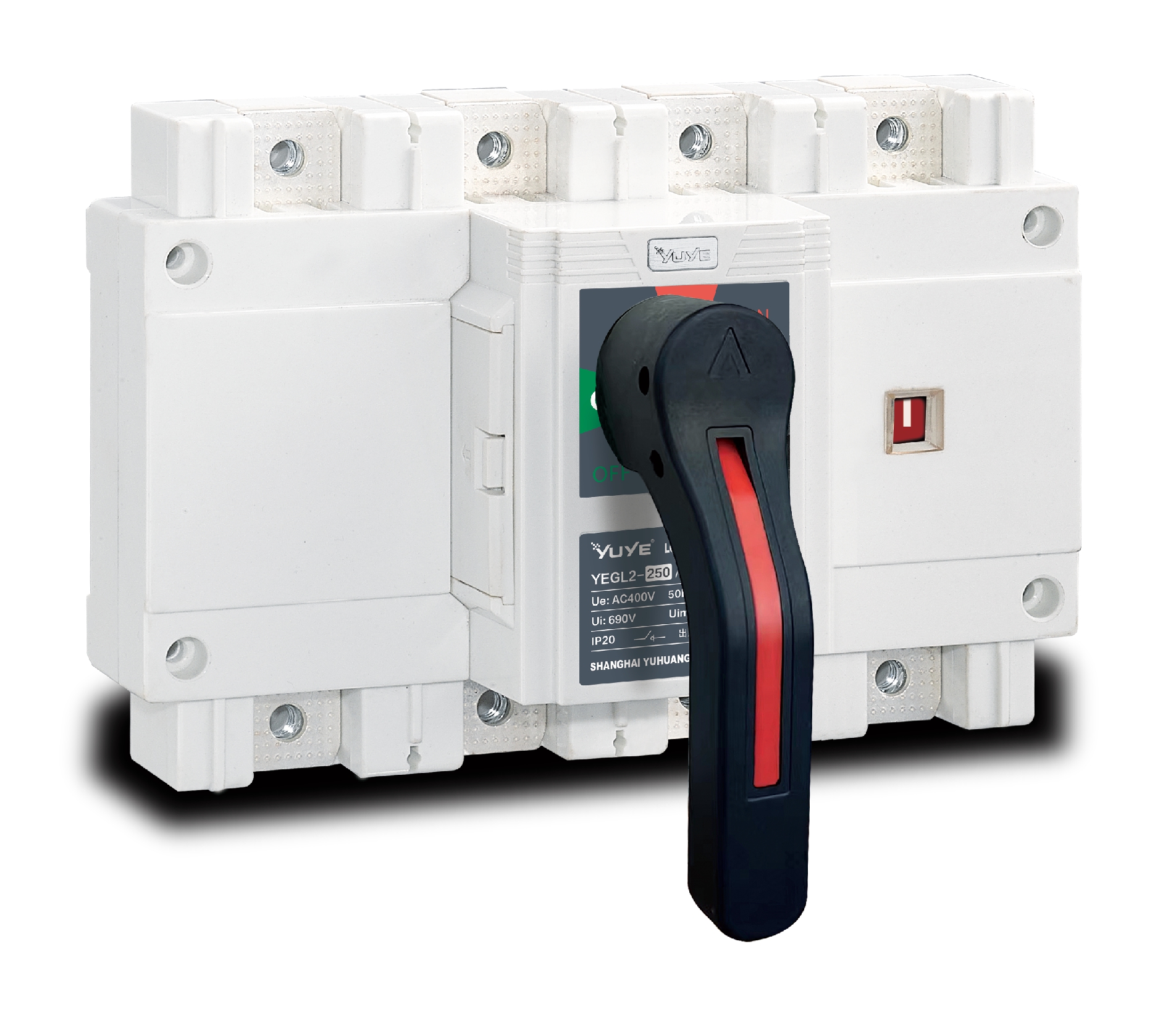 Load isolation switch YGL-250
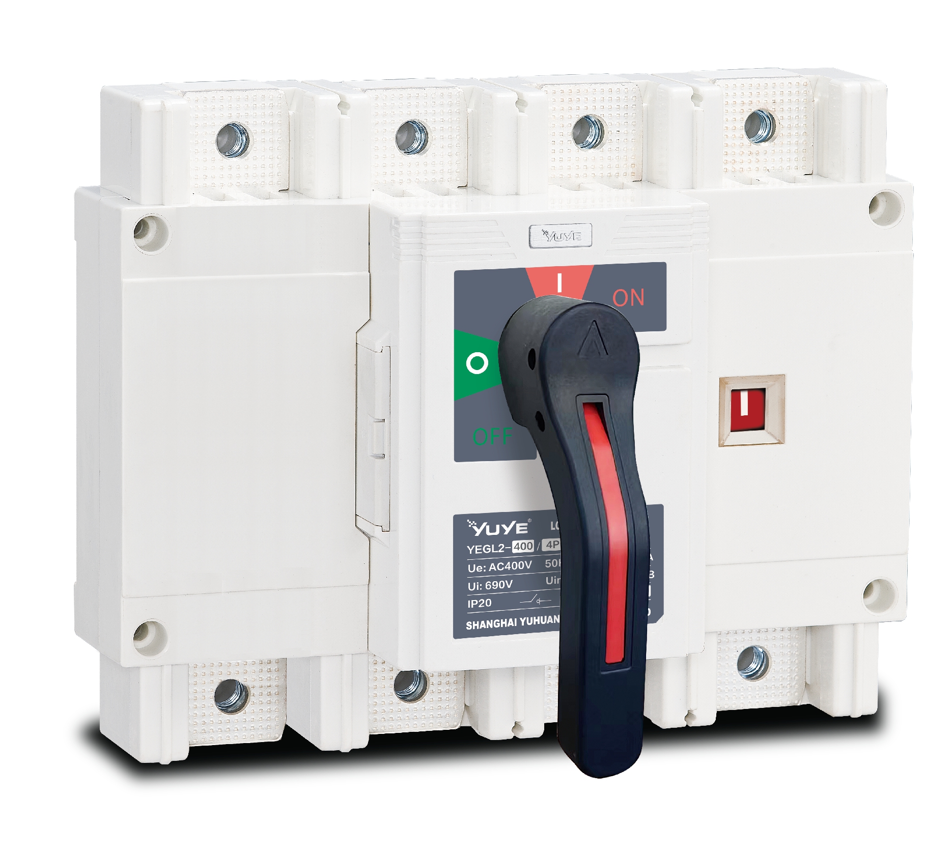 Load isolation switch YGL-400(630)
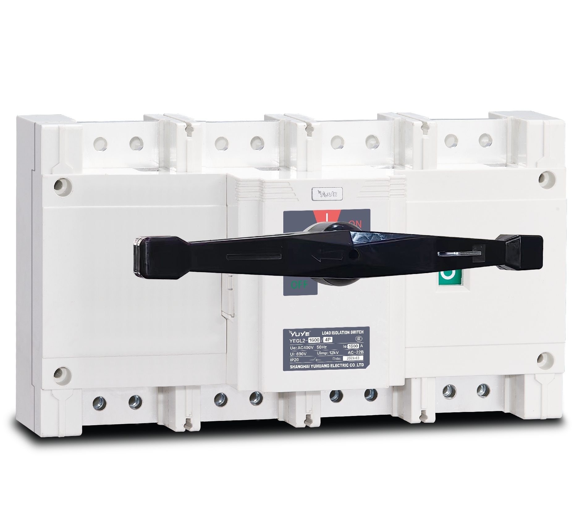 Load isolation switch YGL-1600
 Load isolation switch YGLZ-160
 ATS switch Cabinet floor-to-ceiling
 ATS switch cabinet
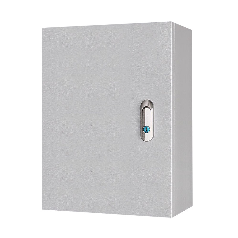 JXF-225A power Cbinet
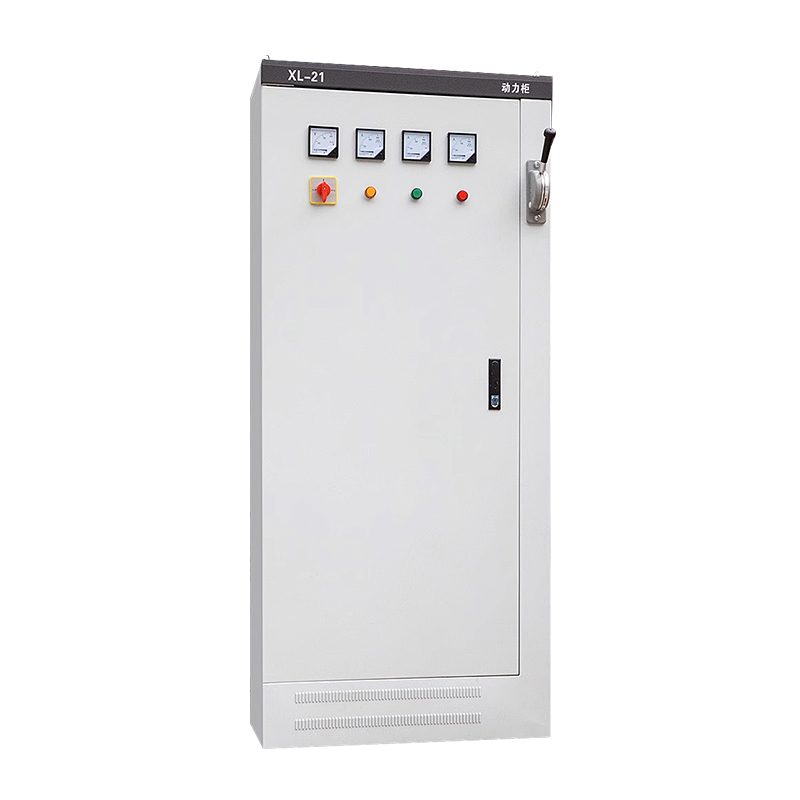 JXF-800A power Cbinet
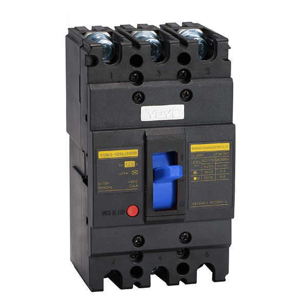 Molded case circuit breake YEM3-125/3P
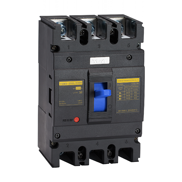 Molded case circuit breake YEM3-250/3P
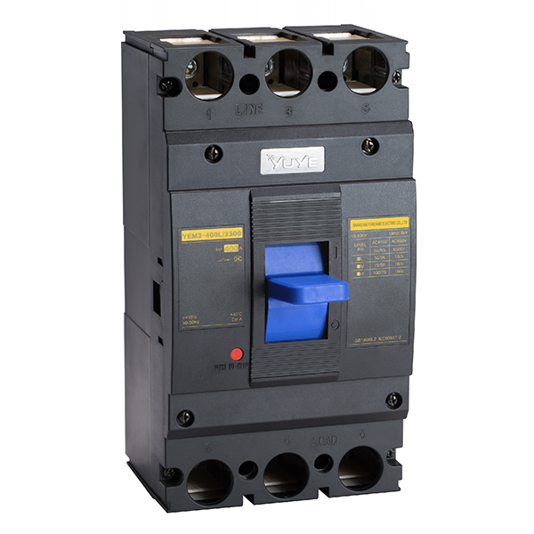 Molded case circuit breake YEM3-400/3P
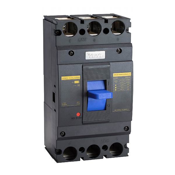 Molded case circuit breake YEM3-630/3P
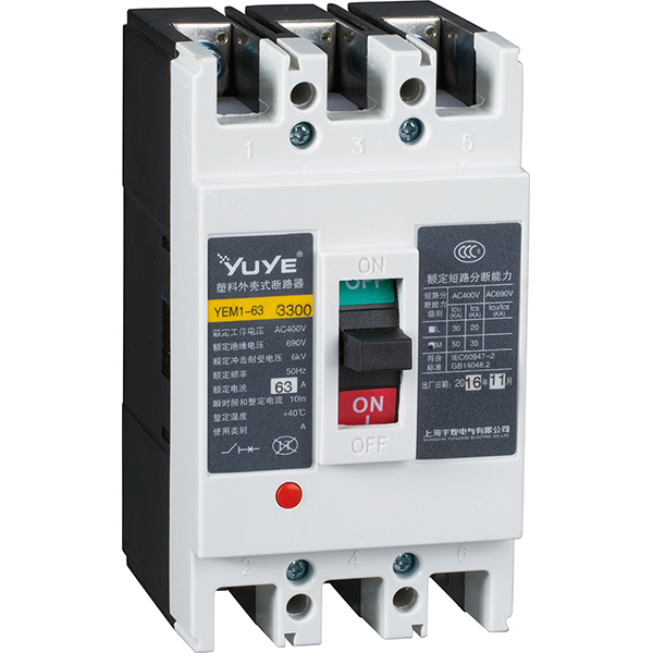 Molded case circuit breaker YEM1-63/3P
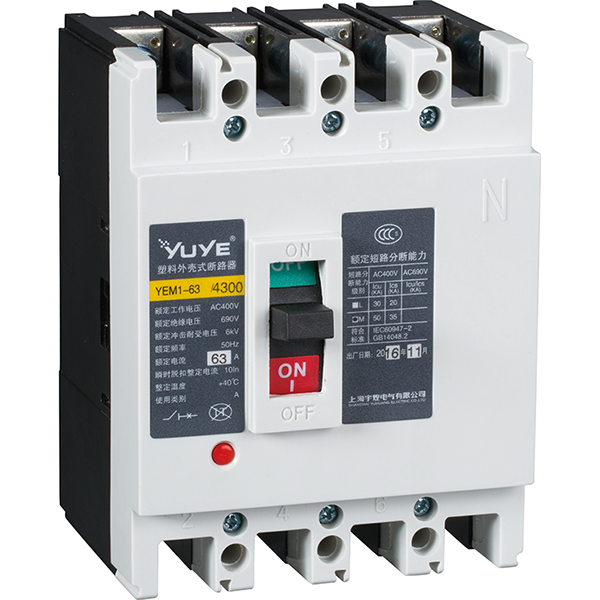 Molded case circuit breaker YEM1-63/4P
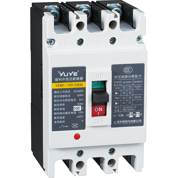 Molded case circuit breaker YEM1-100/3P
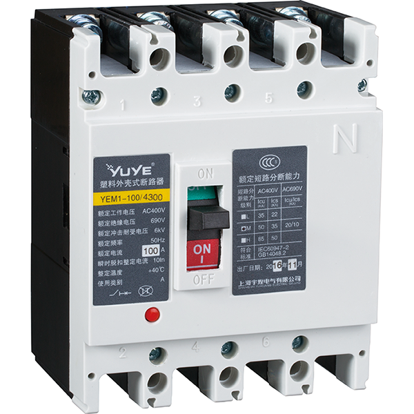 Molded case circuit breaker YEM1-100/4P
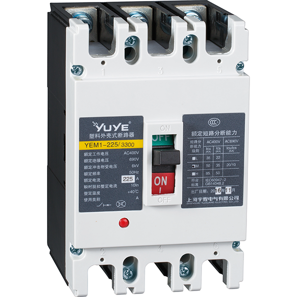 Molded case circuit breaker YEM1-225/3P
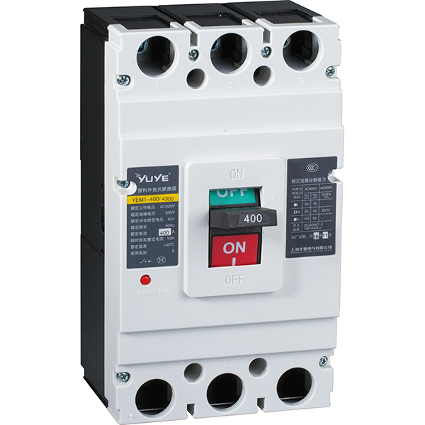 Molded case circuit breaker YEM1-400/3P
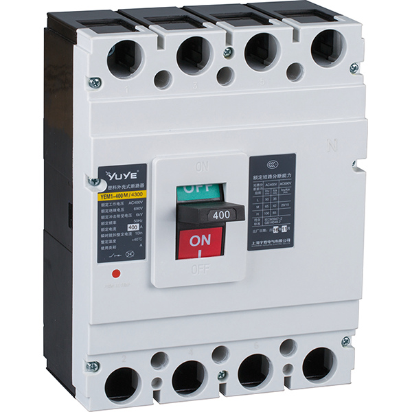 Molded case circuit breaker YEM1-400/4P
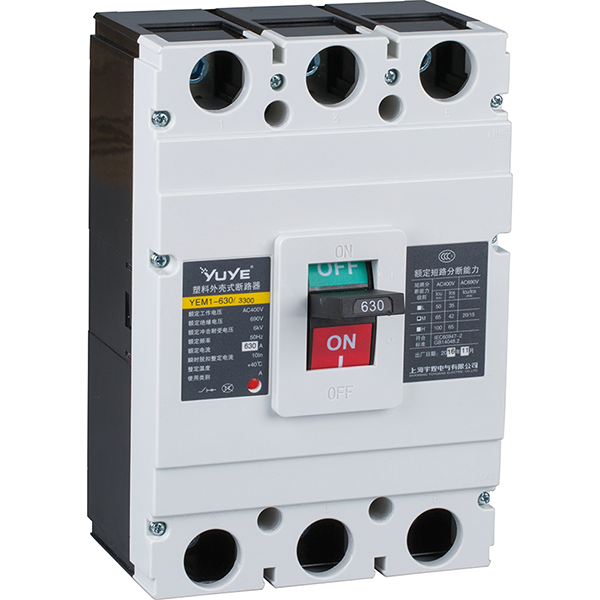 Molded case circuit breaker YEM1-630/3P
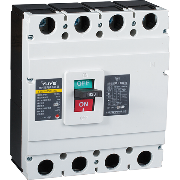 Molded case circuit breaker YEM1-630/4P
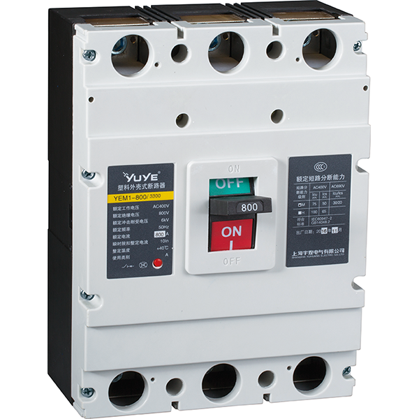 Molded case circuit breaker YEM1-800/3P
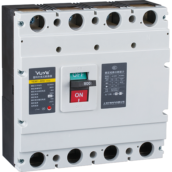 Molded case circuit breaker YEM1-800/4P
 Mold case circuit breaker YEM1E-100
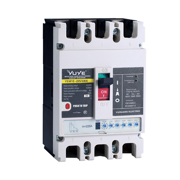 Molded case circuit breaker YEM1E-225
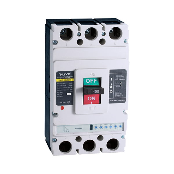 Molded case circuit breaker YEM1E-400
 Molded case circuit breaker YEM1E-630
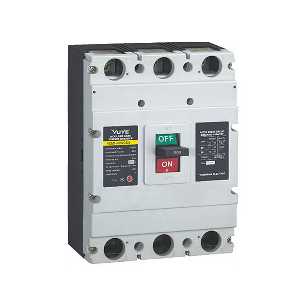 Mold case circuit breaker-YEM1E-800
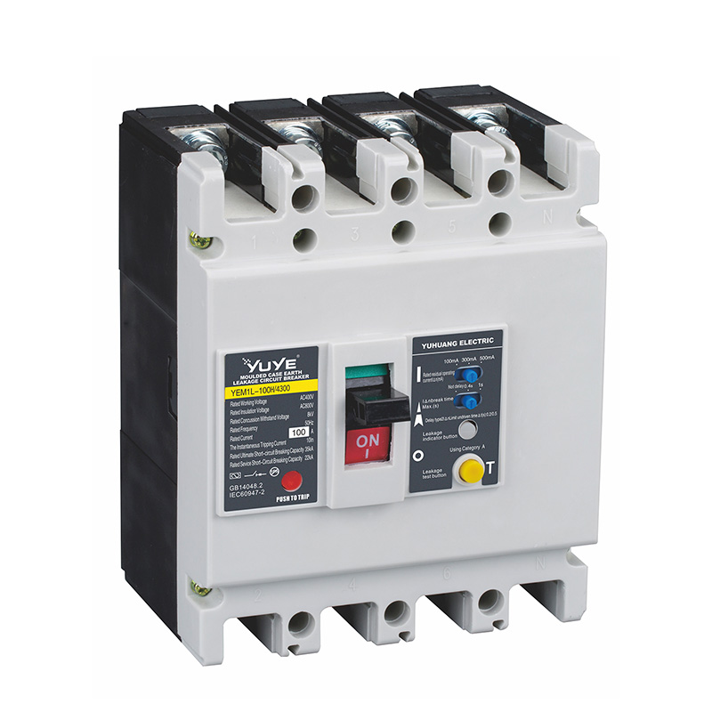 Molded case circuit breaker YEM1L-100
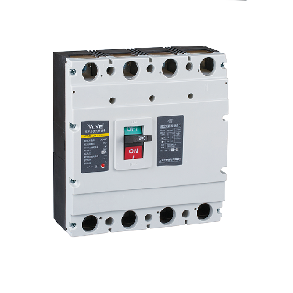 Molded case circuit breaker YEM1L-225
 Mold case circuit breaker YEM1L-400
 Molded case circuit breaker YEM1L-630
 Miniature circuit breaker YUB1-63/1P
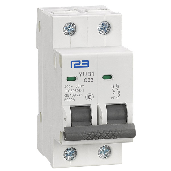 Miniature circuit breaker YUB1-63/2P
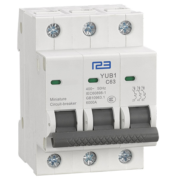 Miniature circuit breaker YUB1-63/3P
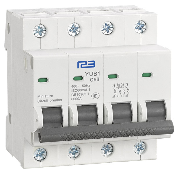 Miniature circuit breaker YUB1-63/4P
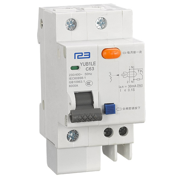 Miniature circuit breaker YUB1LE-63/1P
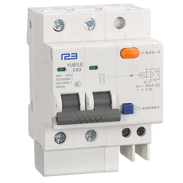 Miniature circuit breaker YUB1LE-63/2P
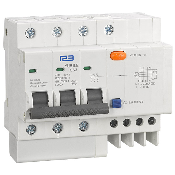 Miniature circuit breaker YUB1LE-63/3P
 Miniature circuit breaker YUB1LE-63/4P
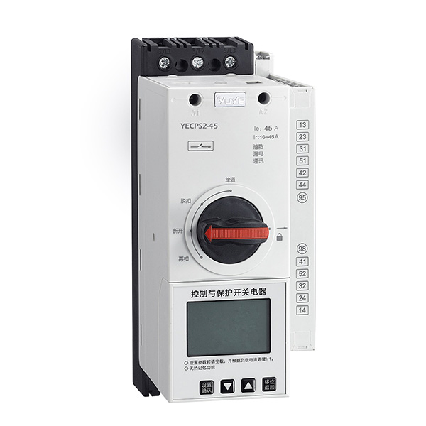 YECPS-45 LCD
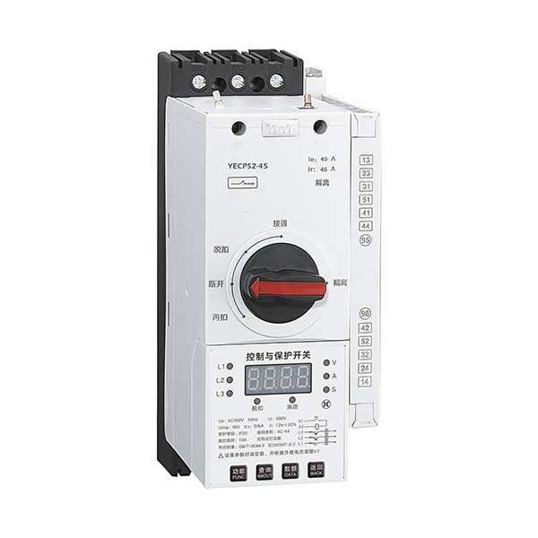 YECPS-45 Digital
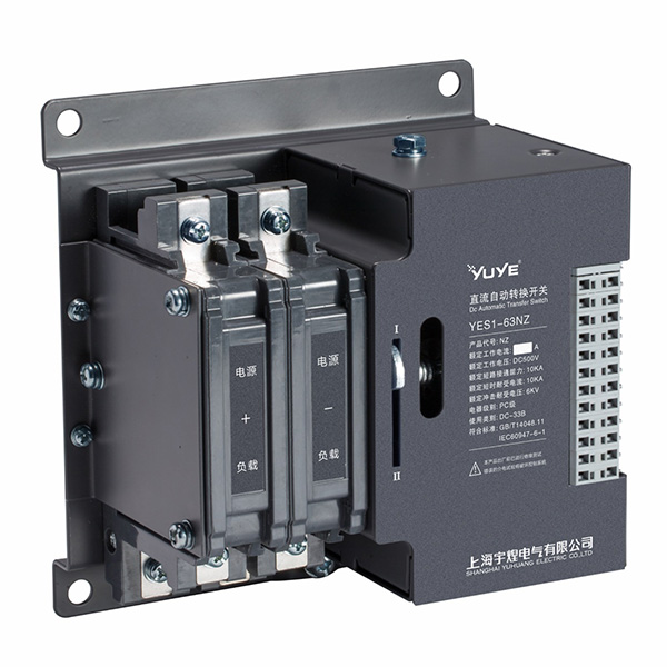 DC Automatic transfer switch YES1-63NZ
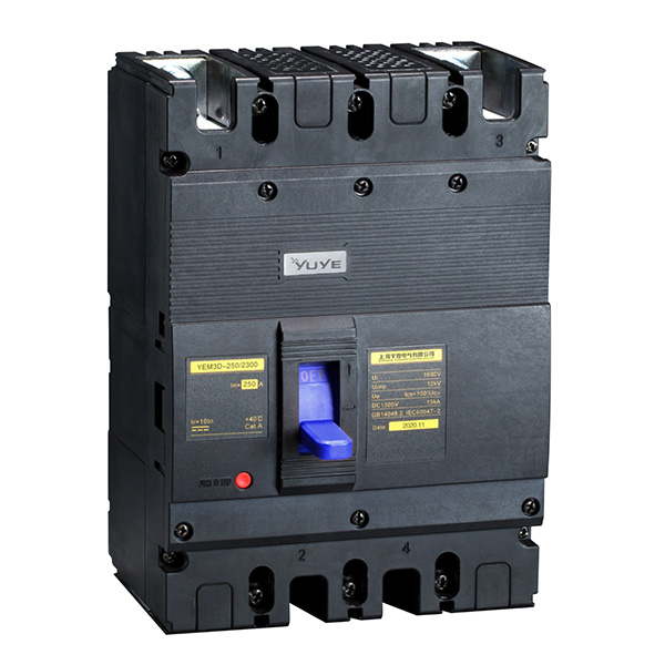 DC Plastic shell type circuit breaker YEM3D
 PC/CB Grade ATS Controller