Whether the neutral line needs to be disconnected when switching between transformer power supply and generator power supply (including the use of dual power automatic transfer switch) depends on a number of conditions or factors, including the type of grounding system of the two power loops, whether the two power loops are connected to the same low-voltage switchboard, and the way the system grounding is set. Whether the power circuit is equipped with RCD or single-phase grounding fault protection, etc., the situation is more complicated. For this reason, IEC standards do not make explicit provisions.
Let’s look at the following different dual-power configuration schemes:
1.Two power supplies installed in the same place, and share the same low-voltage distribution cabinet, the incoming loop or double power transfer switch loop should use 4 pole transfer switch.
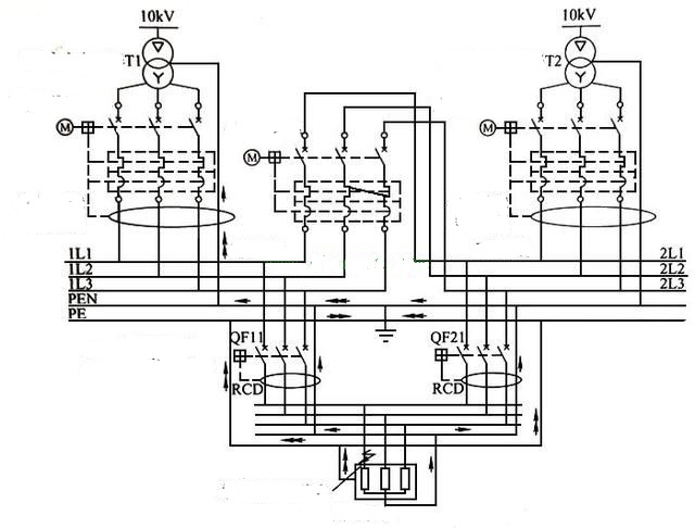
Let’s look at Figure 1
From FIG. 1, we can see that two RCD-protected 3 pole circuit breakers QF11 and QF21 are installed at the front end of the electrical equipment for dual power supply interswitching. We assume that QF11 is closed and QF21 is off.
We can see that whether the single-phase ground fault or three-phase unbalance occurs in the electrical equipment, the single-phase ground fault current or the neutral line current caused by three-phase unbalance may flow through the N line and PE line of the QF21 circuit. Because QF21 RCD protection, QF21 in protection operation state, unable to effectively closing.
And vice versa. In Figure 1, the current flowing through the neutral line or PE line of the QF21 loop is the neutral line current of the non-normal path. The path through which the neutral line current of the informal path flows may form an enveloped loop, and the magnetic field generated in the enveloped loop may interfere with sensitive information equipment, and at the same time may cause the circuit breaker to operate incorrectly. The solution is to use a quadrupole switch for QF11 and QF21 to cut off the path through which the fault current flows.
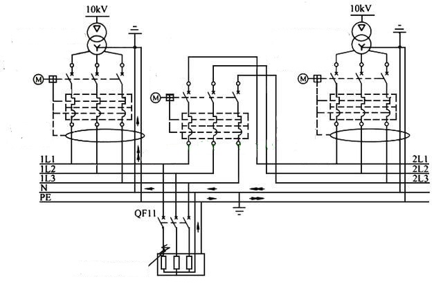
2. Dual-channel distribution transformers are each other’s backup power supply, or transformers and diesel generators are each other’s backup power supply, and the neutral points of transformers and generators are directly grounded nearby. If two sets of power supplies share a low voltage switchboard, the incoming loop should use a 4 pole switch, as shown in Figure 2.
From Figure 2, we can see that the low-voltage distribution network is tn-S earthed type, and the neutral point of the transformer is grounded nearby, leading three-phase, N line and PE line from the transformer to the low-voltage distribution cabinet’s incoming circuit. The low-voltage incoming circuit breaker and busbar circuit breaker are three-pole switches. The incoming circuit breaker is equipped with single-phase grounding fault protection.
In normal use, the circuit breaker is closed and the busbar is open. When the single-phase grounding fault occurs to the electrical equipment on the bus ⅰ, we can see that the correct path is as follows: electrical equipment shell →PE wire → the junction of PE wire and N wire → section ⅰ N wire → Section ⅰ grounding fault current detection → Section ⅰ transformer.
This path is correct. Because of the uncertainty of the N line and PE line combining site, for example, this point can be installed on the two into line loop into the line, so the informal path of single-phase grounding fault current may be: the electrical equipment enclosure – PE line – Ⅱ into line, PE line and N line combining site – Ⅱ period of N line – Ⅱ period of ground fault current – Ⅰ period of N line – Ⅰ transformer ground fault current – > Ⅰ paragraphs. The current flowing along this path is the neutral line current of the irregular path, which may cause the trip of the ⅱ section incoming circuit breaker, making the accident magnify.
The solution is to use a quadrupole switch to cut off the irregular path through which the fault current flows and eliminate the hidden danger of accidents. Similarly, if one of the transformers is replaced with a generator, the generator’s incoming circuit breaker must also use a quadrupole switch. Conclusion: When two power supplies are in the same room (ground) and share the same low voltage distribution cabinet, the low voltage distribution cabinet inlet line and bus loop need to use a 4 pole switch.
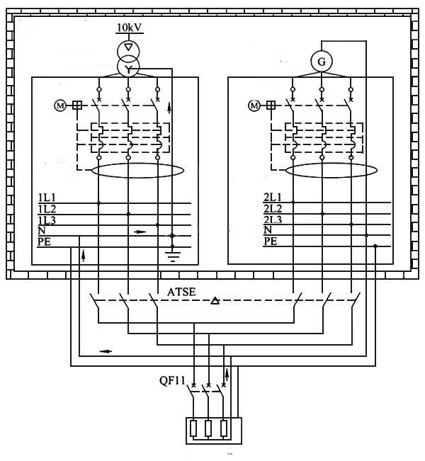
3. The two sets of power supplies are in the same room (common ground), but they do not share the low-voltage distribution cabinet, so the power conversion switch in the secondary distribution equipment can adopt the 3 pole switch, as shown in Figure 3.
FIG. 3 ATSE can adopt three-stage switch when it is a backup power supply. From Figure 3, we can see that the transformer and generator are in the same low voltage distribution station, but they do not share the low voltage distribution cabinet. We see a three-phase imbalance in the load of circuit breaker QF11 of the secondary distribution equipment, and thus a three-phase unbalanced current appears in the neutral line of the electrical equipment.
The path of three-phase unbalanced current is as follows: neutral line N pole of electrical equipment → neutral line OF secondary distribution equipment → neutral line of transformer distribution → detection of grounding fault current of transformer incoming loop → neutral point N of transformer. This path is the conventional path.
Since ATSE is unidirectional in conversion, it can only choose between transformer feed and generator feed, so neutral line current does not appear in unconventional paths. In this case, the ATSE switch can use a three-pole product.


